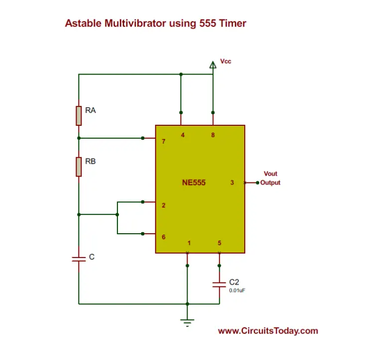
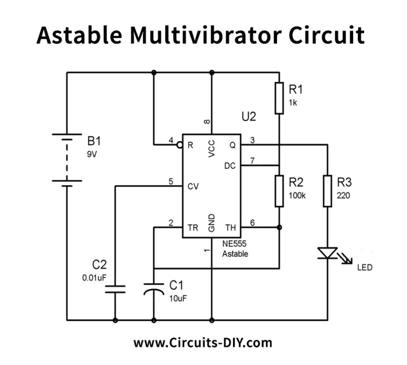
Astable Multivibrator using 555 Timer
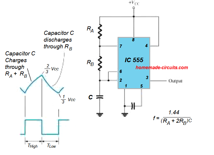
The NE555 timer astable circuit generates a continuous square wave output with a specific frequency and duty cycle. The timing parameters of the astable circuit are determined by the values of two resistors (R1 and R2) and one capacitor (C). The formula for calculating the frequency (f) and duty cycle (D) of the output waveform is as follows:

555 Astable Calculations YouTube
NE555 Timer Astable Circuit Calculator. NE555 is often mentioned as 555, is a highly reliable electronic device. The 555 timer is capable of being used in astable and monostable circuits. NE555 is an integrated circuit, used in time controllers and clock generators, sometimes used for switching on and off of power supplies too.
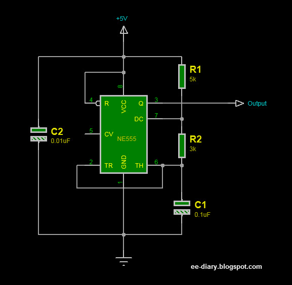
How 555 Timer works in Astable Multivibrator Mode with Simulation eediary
Where: Frequency is the desired output frequency of the astable timer circuit in Hertz (Hz).; R1 and R2 are resistors in ohms (Ω), which determine the charging and discharging times of the timing capacitor.; C is the timing capacitor in farads (F).; Real-Life Application Example. To better understand the practical application of the IC 555 astable timer, let's consider an example.
555 Astable Multivibrator Calculator Soldering Mind
Free Shipping Available On Many Items. Buy On eBay. Money Back Guarantee! But Did You Check eBay? Check Out Top Brands On eBay.
555 Timers Astable Multivibrator Configuration YouTube
This spreadsheet calculates the complete design of a TLC555 timer-based astable circuit given the timing capacitance, on time, and desired duty cycle. Resistor values are calculated to the nearest 1% value.. TLC555CALC — TLC555 Design Calculator. close. Latest version. Version: 01.00.00.0A. Release date: 04 Jul 2011. open-in-new. View all.
Calculadora de tiempos con 555 Gzalo
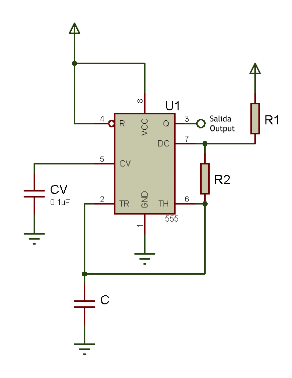
555 Timer Astable Circuit Calculator. In this 555 timer Astable calculator, enter the values of timing capacitor C and timing resistors R1 & R2 to calculate the frequency, period and duty cycle. Here the time period is the total time it takes to complete one on/off cycle (T 1 +T 2), while Duty cycle is the percentage of total time for which the.
555 Timer Astable Multivibrator Circuit
Calculate and visual simulate operating modes of the 555 (LM555, NE555) integrated circuit timer chip. 555 Timer A-stable Oscillator Circuit permalink to this solution Mode. astable monostable R1 (kΩ) R2 (kΩ) C1 (μF) Frequency:. For an example of a 555 circuit hooked up with Arduino and Processing,.

555 astable circuit calculator doorbell wire
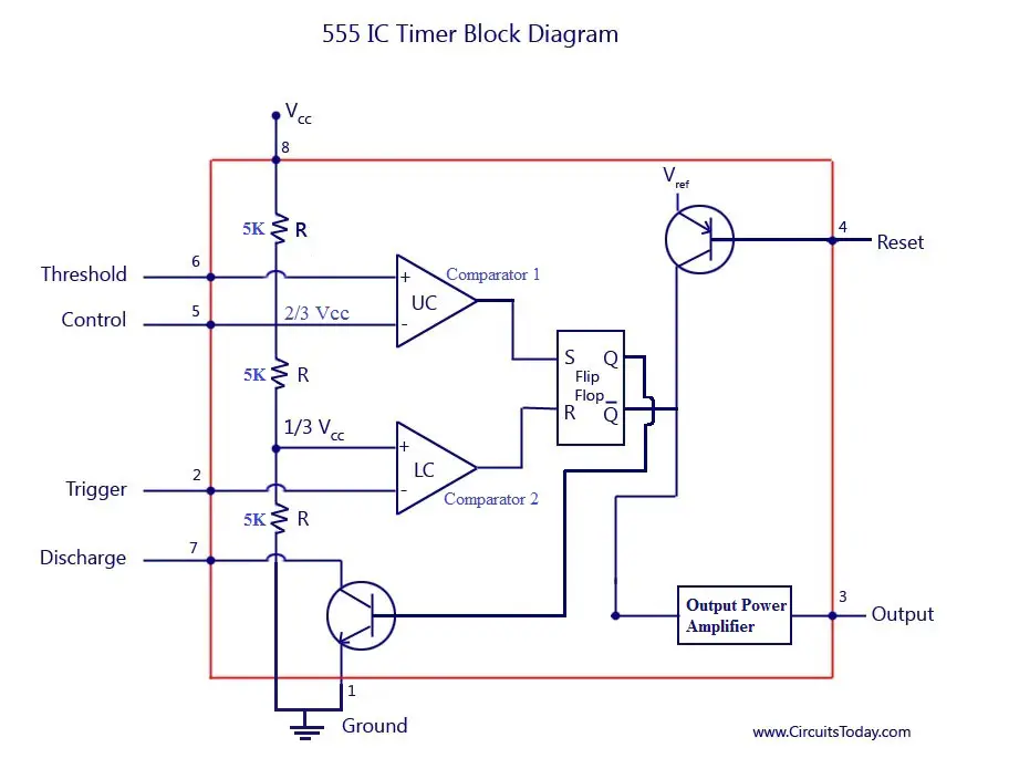
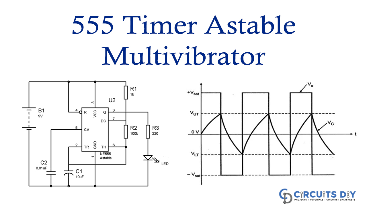
555 Timer Calculator Overview. The 555 timer shown above is configured as an astable circuit. This means that the output voltage is a periodic pulse that alternates between the VCC value and 0 volts.
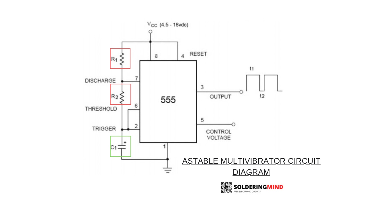
Astable 555 Timer Circuit Diagram
555 Astable Circuit Calculator. The 555 timer is capable of being used in astable and monostable circuits. In an astable circuit, the output voltage alternates between VCC and 0 volts on a continual basis. By selecting values for R1, R2 and C we can determine the period/frequency and the duty cycle. The period is the length of time it takes for.
IC 555 Astable Calculator
NE555 Astable Circuit Calculator. In astable mode, the NE555 can be used to create an oscillating output between V CC and 0V. All that is needed is a setup like in the following schematic: By selecting proper values for R_1, R_2 R1,R2 and C C, we can determine the frequency and duty cycle of the oscillation: A period is the time for one full on.
Online 555 timer calulator Astable component and frequency calculator
Using the 555 Timer Calculator involves the following steps: Select Operating Mode: Determine whether the 555 timer is configured in monostable, astable, or bistable mode. Input Component Values: Enter the relevant resistor and capacitor values based on your circuit requirements. Click Calculate or Submit: Initiate the calculation by clicking.

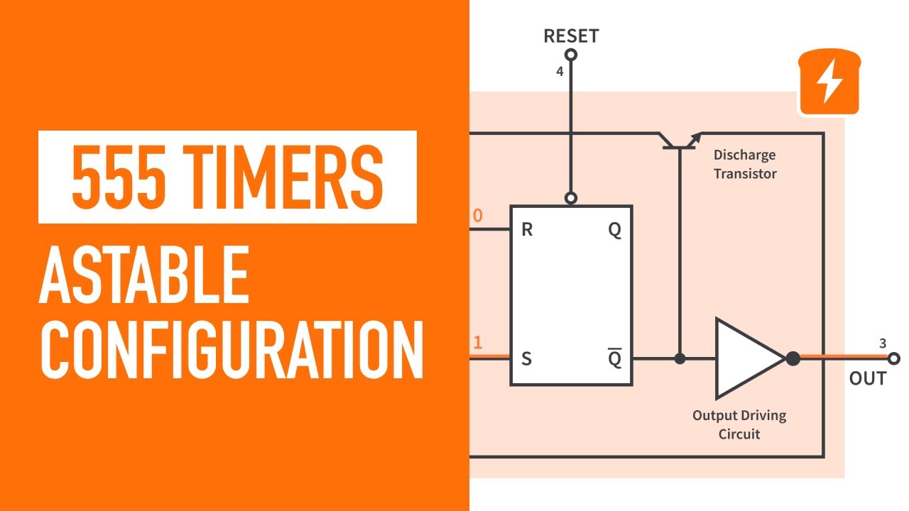
555 Timer 4. Astable Multivibrator Configuration … CircuitBread
To use the calculator, simply enter the resistance and capacitance values, and the calculator will calculate the frequency, time period, duty cycle, time high, and time low of the output from an 555-timer astable circuit. This calculator will help you design an oscillator using a 555 timer IC. Just remember these three things before you begin.

Astable multivibrator circuit LM555 to register the changes of the... Download Scientific Diagram
555 Timer Calculator. Use this 555 Timer calculator to find the output based on you resistor and capacitor values. You can choose between astable mode and monostable mode. The astable mode will give you a frequency calculator plus time high/low. The monostable calculator will give you the output pulse duration.

Timer 555 Astable Formulas
555 Timer Astable Circuit Calculator. In this 555 timer Astable calculator, enter the values of timing capacitor C and timing resistors R1 & R2 to calculate the frequency, period and duty cycle. Here the time period is the total time it takes to complete one on/off cycle (T 1 +T 2), while Duty cycle is the percentage of total time for which the.

555 astable circuit calculator doorbell wire
The output frequency (f) of a 555 timer astable circuit can be calculated using the following formula: f=1.44 /(R1+R2). Our 555 Timer Astable Calculator is a valuable tool for electronics enthusiasts and hobbyists working with 555 timer astable circuits. By quickly and accurately calculating the output frequency, it simplifies the design and.
555 Timer Astable Multivibrator Circuit
555 Timer Calculator This page is very useful when creating 555 timer circuits. it will allow you to calculate the frequency and duty cycle. Astable 555 Square Wave Calculator In an astable circuit, the output continually switches state between high and low without any intervention from the user. The duration of the high and low states are.
